| SHIFTY BUSINESS |
 |
 |
INSTALLATION OF JERRY?S
SHIFT IMPROVER KIT
IN A 1995 4R70W THUNDERBIRD
By Anthony Frusco
A-Train
NOTE: This
information is based on a pre-modified main control unit and is a supplement to
Jerry's thesis/novel. This report is to show you how to remove the main control
and accumulators for Jerry?s shift improver kit.
Last
Update: 1-9-02 Applications include any 94-?97 3.8L/4.6L T-Bird or Cougar.
The
parts/materials required to perform the installation.
Jack
(hydraulic, two preferred)
Jack stands
and/or ramps
Qaulity
Snap ring/retaining ring pliers (with assorted tips)
Metric sockets (deep and regular)
18mm, 10mm,
8mm, etc.
Flat-head
screwdrivers (medium size)
1/4",
3/8", and 1/2" ratchets and extensions
15 qt.
capacity catch pan
6-ft. of
3/8" ID hose or equivelant
5/16"
upper radiator fittings
Inch-pound
torque wrench
Needle-nose
pliers
Regular
pliers
Brake
cleaner (F6AZ-2C410-AB), 12 oz. can
Paper
towels and shop rags
Speedy dry
or Kitty litter
STEP #1:
Apply the emergency brake and open the hood, then disconnect the fan wiring
harness.NOTE: This is because the
electric fan may come on at any time, even while the engine is off. Place a
suitable 12-15 qt. container near the front of the car. You may wish to raise
the vehicle on jack stands or ramps at this time.
STEP #2:
Remove the upper radiator transmission line fitting from the radiator fitting.
Attach a 5/16" adapter to the radiator to allow connection of a 6 ft.
long, 3/8" ID hose (if necessary). DO NOT attach the hose to the metal
transmission line. Run the hose from the fitting to the large capacity pan on
the ground. Secure the hose to the fitting properly with an adjustable clamp.
If you
are installing a transmission cooler, follow the procedure below.
Remove the
upper radiator transmission line fitting from the radiator fitting. Remove the
radiator fitting that is threaded in the radiator. Install a new 5/16? inverted
flare to ?? male NPT fitting into the radiator. Then install a flared fitting
with a 3/8? hose barb into the inverted flare fitting. Use thread sealant
between the two fittings. Push a hose over the barbed end and secure it with a
hose clamp. Run the hose to the large container on the ground. Note: If you are
using empty gallon water containers. Generally, you will get one full gallon
and a ? gallon of ATF out this way.
STEP #3:
Start the engine and let the ATF pump into the pan. This process takes only a
few minutes and requires two people. You may slightly rev the engine to
activate the pump at a higher capacity, but do not exceed 1,200 rpm. Once the
ATF fluid starts spitting or the flow rate slows significantly, stop the engine
quickly. Failure to stop the engine could result in transmission damage as the
pump sucks up air. Re-install the transmission line to the radiator fitting and
discard the 3/8" ID hose. NOTE: Now is an excellent time to install an
auxiliary transmission cooler.
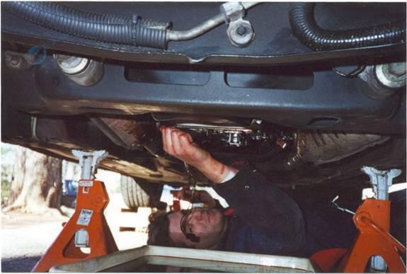
STEP #4:
Safely support the vehicle on jack stands and/or ramps, then move the large
capacity pan to under the torque converter. Remove the rubber access plug from
the bell housing shield using a flathead screwdriver.
You will
have to rotate the engine to align the torque converter drain plug with the
access hole in the bell housing shield. The easiest way to do this, is to place an 18mm socket and ?? drive (or breaker
bar) over the crankshaft pulley bolt. Then rotate the crankshaft CLOCKWISE
until you see the drain plug through the hole in the bell housing. Another way
to do this, is to disconnect the coil pack electrical
connectors. Then crank the engine, to align the drain plug (two people make
this task easier).
Remove the
torque converter drain plug and allow the ATF to drain. It will take about 30
minutes to completely drain the torque converter.

STEP #5:
Remove the transmission pan by loosening the 14, 10mm pan bolts. By draining the
transmission through the cooler lines, the pan will therefore have less than a
quart of ATF in it. Drop the pan carefully to avoid spilling any remaining ATF.
Remove the filter assembly and verify the filter seal was removed from the
bore. Drop the filter into the pan. Discard the plastic plunger that may be
floating in the pan. It was used to plug the dip stick hole during the factory
assembly. Allow the transmission to drip thoroughly before removing the main
controls (valve body).
STEP #6:
While the transmission and torque converter are draining together into the
large capacity catch pan, remove the electrical connectors to; the TCC (torque converter clutch) solenoid
- 7G136, shift
control solenoids - 7G484, EPC (VFS) solenoid - 7G383, and the TOT
sensor, the plastic tab on the main controls - 7H141.
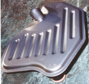
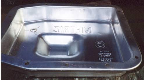
STEP #7:
Transfer the magnet from the original '94-'95 4R70W transmission pan to the new
'96 deep sump pan (F6AZ-7A194-A). There is also a
'98 deep sump pan with a drain plug available (F8UZ-7A194-AA).
NOTE: This step does not apply to '96-'97 T-Birds and Cougars, since they
already have the deep sump transmission pan and corresponding filter assembly.
Be sure to clean the magnet thoroughly with the brake cleaner spray. NOTE: DO
NOT spray near the vehicle as the overspray will attack the paint. Be sure to
wear safety glasses when using the brake cleaner spray. Clean out the new
transmission pan as well to remove any debris that may have settled during
packaging or shipment. Place the magnet in the same spot as it was located in
the original pan. Place the pan to the side for the time being. NOTE: If you
are re-using the original pan, it must be thoroughly cleaned out as well.
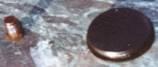
STEP #8: Remove the 25-8mm main control (valve body)
bolts. Start with the EPC/VFS solenoid bracket and remove that bolt (1), then
the bracket. Then remove the 12 bolts around the valve body plate or the
shorter length 8mm bolts. Finally, remove the 12 longer length 8mm bolts inside
the valve body plate. Note one of the bolts retains the Rooster Comb Spring
(with the roller attached to it). Make a drawing or write down a brief
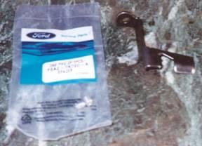
description of the manual valve and the detent lever set-up.
The manual valve is the
valve shown here in this photo. The detent wheel?s pin attaches in the FIRST
section on the valve (the very thin part before the c-clip ring).
Carefully
lower the valve body into the original transmission pan or have somebody ready
to receive it. It will be heavier than you expect. Move it to the work bench.
Be careful, as the 2-3 accumulator retainer and spring may fall out and drop
into the fluid pan below. NOTE: To perform the main control modifications, your
working environment should be as sterile as possible and free of debris. Once
you get the main control down and on the bench, you may wish to remove the
shift solenoids from their bore. This is optional, but it does make the main
control easier to work on. To remove the shift solenoids, loosen the bolt
retaining them. Then wiggle the solenoids back and forth while carefully
pulling upward. The solenoids will pull out without much effort. Inspect the
snout of the solenoids for cracks. If there are any, replace the solenoid pack
with a new one. Use the p.n. that is on the pack. Do not re-use the solenoids
if the snouts are cracked.
I will not
go into detail on how to modify the main controls in this report, considering
they may vary from vehicle-to-vehicle per application. Consult with my ?Valve
Body How-To? report or Jerry's thesis/novel for exact instructions on
how to perform the changes to the main controls (shift improver kit). This also
applies to the Inject Tech?s pre-drilled separator plate. Perform the
modifications at this point.
STEP #9:
Modify the main controls or swap the pre-drilled separator plate. Refer to the ?how-to? report.
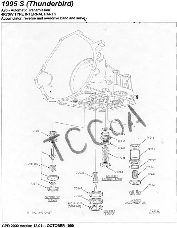
STEP #10: 2.7" OVERDRIVE SERVO (if applicable). To remove the OD Servo (see the CPD
Drawing for the bore location) the valve body must be removed before hand. When
you remove the main controls, you will find a hole in the case next the OD
servo bore. The hole goes through to the barrel of the transmission where you
will see the OD band. If you remove the OD Servo and do not anchor or hold the
OD band, it can move when you attempt to re-install the OD servo. If this
occurs, you will not have access to the Overdrive gear (4th).
BEFORE you
remove the OD servo, use the Rooster Comb Spring (the flat metal part with the
roller on the end of it), p.n. 7E332, to wedge against the OD band. Install it into the
hole next to the OD servo bore so that the roller is sticking out. Wedge it
against the back of the OD band and the transmission case, but do not damage
the Rooster Comb Spring. Remove the snap ring retaining the OD servo using
small screwdrivers or snap ring pliers. Next, remove the OD servo from the
bore. If
you should hear/feel the OD band fall, do not panic. You can push up on the
pocket once the OD servo is removed from the bore. You will quickly learn that
when you push up on the pocket, the OD band moves and the hole on the side will
no longer be visible. The tip of the OD servo must contact the
pocket
(dimple) in the band.
While still
holding the OD Band in place with the Rooster Comb Spring, install the new
2.7" OD servo (F75Z-7H188-AA) and the appropriate return spring
based on your horsepower level. NOTE: The 2.7" OD Servo does not have the
metal sleeve like the stock 2.5" OD servo. Simply place the NEW return
spring p.n. F87Z-7F201-AA over the servo
piston so it sits in the perch. Apply some fresh ATF to the rubber seal around
the edge of the new servo, then install the 2.7" OD servo into it's bore. Be sure to install it so it does not enter on an
angle.
In the bore you will notice two grooves. The snap ring (7384) must be installed in the second groove. To do
this, it may be necessary to use a hydraulic jack, with a large deep socket to
help hold the servo up into the bore while you install the retaining ring (see
Reverse Servo). Place the large diameter deep socket (i.e.
1-1/16")
on the tip of the jack mount and raise the jack height to reach the OD servo
bottom. Then slowly increase the height until the second groove in the bore is
visible. DO NOT over force the servo
up into the bore with the hydraulic jack, or damage to the transmission could
occur. Once the snap ring is installed, you can remove the Rooster Comb spring
from the hole.
ADDITIONAL
NOTES:
In Step
#13, the "shifter roller" is the Rooster Comb Spring, p.n. 7E332. Obviously, it needs to be re-installed on
the valve body. You can also use a screwdriver to perform this step.
You cannot
use spring p.n. F3LY-7F201-A
or the stock 2.5? OD servo spring with the 2.7" OD servo.
STEP #11: REVERSE SERVO (if applicable). To
remove the reverse servo (the largest bore), remove
the retaining ring with a small screwdriver. The servo will pop out fairly
easily. Be sure not to lose the return spring (7D031) that goes on the top of
the servo or the retaining clamp between the retaining ring and the servo
(7D036). Apply some fresh ATF with your finger to the rubber seal before
installing the servo. Install part number E0AZ-7D189-A
and it has only one groove (or ring) on the servo. Be sure to re-install the
retaining clamp and return spring as well. It may be necessary to use a 1-1/16"
socket and 2" extension as well as a hydraulic jack to hold the new
reverse servo up in its bore while you install the snap ring. DO NOT OVER-APPLY
PRESSURE TO THE SERVO with the hydraulic jack or damage to the transmission
could occur.

STEP #12: 1-2 ACCUMULATOR PISTON.
To remove the 1-2 accumulator piston, remove the snap ring using snap
ring/retaining ring pliers. WARNING: The 1-2 accumulator pistons spring and
snap ring may eject with extreme force when you release the snap ring. This
depends on the accumulator spring set-up your vehicle has.

Remove the snap ring with a good pair of snap ring
pliers.
The 1-2
accumulator piston should pop out of its bore fairly
easily. If not, push up on it with your fingers or an extension to re-act the
return spring. Use Scotch-Brite on the accumulator bore if it is slightly
scored. Spray brake cleaner to clean out the bore before you install the new
updated accumulator piston. Allow the brake cleaner to evaporate before
installing the new piston. Apply some fresh ATF with your finger to the rubber
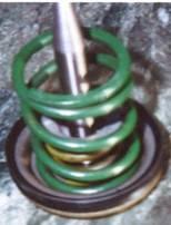
seals on the accumulator piston before installing it.

Photo from Jerry?s
thesis.
Install the
new rubber bonded accumulator piston (F7AZ-7F251-AA)
and use the blue return spring on the top (F75Z-7F284-AA).
Do not install the original spring on the bottom of the piston. Leaving the
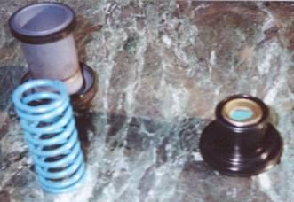
spring out will firm up the 1-2 upshift. Re-install
the accumulator retaining cover (7F247)
followed by the snap/retaining ring (7384). The
orientation of the accumulator cover can be confusing if your
not paying attention when it?s removed. Always look for the marks in the spring
perch inside the cover, to tell you which end is up.
Obviously, the marks mean the spring was rubbing and that end is up. There is
also a part number stamped into the cover, the p.n. goes down. Use the
snap/retaining ring pliers to re-install the snap ring.
STEP #13: 2-3 ACCUMULATOR PISTON.
To remove the 2-3 accumulator piston, simply remove
the main controls (valve body). The retainer and return spring will fall out
freely (the original piston is made of all-aluminum). Use a pair of needle nose
pliers to pull the 2-3 accumulator piston out from it?s
bore. Clean out the bore with brake cleaner and allow some time for it to
evaporate. Apply fresh ATF with your finger, to the seals on the 2-3
accumulator piston. Then install the new rubber bonded
2-3 accumulator piston (F7AZ-7H292-AB).
Do not re-install the stock return spring, or any return spring for that
matter. You will have to bend the tabs out on the retaining clamp (7B264) SLIGHTLY with a pair of pliers in order
to keep the 2-3 accumulator in it's bore.
STEP #14: EPC(VFS) Solenoid (if applicable). To remove the old EPC solenoid, you must remove the retaining nut from the shifter
linkage using a 13/16" wrench. There is also a small pin that must be
removed using needle-nose pliers. Do not lose the small pin as it will be
re-installed later.
Carefully
remove the EPC solenoid and replace
it with the '96 version (F6AZ-7G383-AA).
Re-install it in reverse order. You must use a new style EPC bracket (F6AZ-7H111-A)
with a '96 and newer style main control unit. NOTE: The '96-'97 T-Birds and
Cougars already have the new style bracket.
Please note
that a different higher pressure solenoid exists as well (XL3Z-7G383-AA).
However for pre-1998 models (through 1997), you must cut the
pigtail from the wiring harness and solder the wires (or crimp connect as shown
in Jerry's thesis) to the new style EPC solenoid's connector. This was
done because of the wireless connectors (circuit board) used in the 1998 model
4R70W transmissions. Note: If you are installing Jerry?s Shift Improver kit,
you do not have to change the EPC solenoid. Replacing the EPC solenoid is
optional and for high HP applications. You do not need to use the higher
pressure solenoid, its optional. DO NOT under any
circumstance adjust the screw in the rear of the EPC solenoid, or transmission
damage could occur.
STEP #15:
Re-install the main controls (valve body) at this time. Be sure that the 1-2 Accumulator, 2-3 Accumulator, Reverse Servo, and EPC
solenoid are up in their proper locations (especially the 2-3 accumulator)
before proceeding. There is also a little black cone-shaped filter that goes
into the transmission case near the rear of the transmission (towards the
driveshaft). Be sure that it hasn't fallen out as well. DO NOT LEAVE IT OUT.
Verify that you have properly performed the main controls (valve body)
modifications before continuing. NOTE:
If you are installing a '96 and newer style main control (suggested is '99) in
an older style case ('94-'95 4R70W), you must install two pilot sleeves (F6AZ-7K720-A), they are sold in a package of
two. Place them over the two black tips on the top of the main controls and
install the assembly into the transmission case.
You must
align the manual valve with the detent wheel?s pin. See the previous photo. The
pin gets inserted into the FIRST section on the manual valve (the thin part
before the c-clip ring). The Rooster Comb spring?s roller should be in the
fourth (4th) detent when the transmission is in Park. You must do
this correctly or you will not have access to all gear selections.
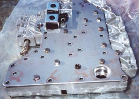
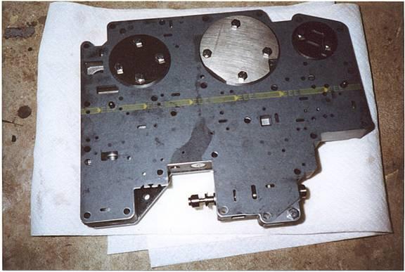
You can see the
shift solenoids in this photo. This photo may vary from your main control, its just for reference.
STEP #16:
Spray the inside of the transmission case with brake cleaner spray to remove
the ATF fluid from your work area. Install the valve body in the reverse order
as it was removed. Carefully thread two of the longer 8mm bolts into the
opposite ends of the main controls, to hold it in place. Re-install the
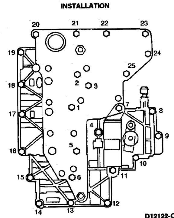
remaining 23 bolts that retain the valve body. Torque the bolts to 90 in.-lbs.
Hook up the electrical connections to the various sensors. Here is the check
list; TCC (Torque converter clutch) solenoid,
Shift solenoids, EPC solenoid, and black plastic tab (7H141). Be careful not to incorrectly hook up the
solenoids to the wiring harness or transmission damage could occur. See the CPD
drawing below for details. The following
shows you the torque sequence for the main control bolts.

IMPORTANT:
Re-install and tighten the bolt that secures the shifter linkage if you have
removed the EPC solenoid. Then install the pin and roller. Be sure to verify
the shifter still works and you can remove the key in Park. Turn the key to the
on position (DO NOT start the engine) and move the shifter through the gears,
then remove the key. If you cannot remove they key in Park, you must re-adjust
the linkage. This step is not difficult, but it is important.
STEP #17:
Install the '96 filter (F6AZ-7A098-A)
assembly into it's bore in the main controls. Regardless of which year transmission you have ('94-'97) you have
to install the '96 filter. Apply fresh ATF with your finger to the
filter seal before installing it.
STEP # 18:
Install the '96 (or '98) deep sump transmission pan
(F6AZ-7A194-A). NOTE: The '96-'97 T-Birds and
Cougars are equipped with the deep sump pan from the factory. Re-use the
original transmission pan gasket ('94-'97), provided it is not ripped or
damaged. It is fairly durable and the '96 pan actually states, "This pan
is equipped with a re-usable gasket". Bolt up the pan using the original
14, 10mm bolts. Tighten the pan bolts up to 120 in.-lbs. of torque. IMPORTANT:
If you have a cork style gasket instead of the factory gasket, it is highly
recommended you upgrade to the p.n. F2VY-7A191-A. This is also the p.n. for the
gasket in case you rip or damage your re-usable one.
STEP # 19:
Re-install the torque converter drain plug and torque it to 22 lbs-ft. or 30
N-m (this is hand tight). Then pop the rubber seal in the bell housing shield.
NOTE: Re-install the fan wiring harness at this time.
STEP #20:
Fill the transmission through the dip stick tube. Add 6 qts. of
MERCON-V ATF (XT-5-QM)
at first. Hold the brake firmly and start the engine. Move the shifter level
through the gears, stopping at each indent or position. Do not panic if you do not feel the
transmission engage into gear. Stop the engine and add 6 more quarts of MERCON-V ATF to the dip stick tube.
Stop again at 10 qts. and repeat the process listed
above. The 4R70W holds 12-13 quarts of ATF fluid, do not over-fill the
transmission. NOTE: If you have an auxiliary transmission cooler, you will
require 13-14 quarts of ATF.
STEP #21:
Inspect the pan and transmission for leaks. Then carefully lower the vehicle to
the ground. Start the engine and allow the transmission to warm up to normal
operating temperature, listen for strange noises or smells. If you see smoke,
do not panic, it is just the ATF burning off of the exhaust parts. Once the
engine has warmed, rev the engine slightly (to activate the pump). Then move
the shifter lever through the gears. Hold each gear for at least one second
before changing to a new indent or position. You should feel the transmission
engage each gear followed by a decrease in engine rpm.
STEP #22:
Road test the vehicle. Observe the shifting, firmness of the shifts and rpm of
the shift points. Also check reverse and forward gear characteristics.
Accelerate to 45-50 mph and press the Overdrive "ON/OFF" button
located on the shifter handle. Verify that the transmission has engaged 4th
(OD) gear and that the vehicle accelerates properly. Verify you can manually
shift the transmission in the 1-2 and 2-3 positions.
STEP #23:
Re-check the clamps on the transmission cooler lines and auxiliary cooler.
Check to make sure you have no leaks, especially under the pan or TC. Verify
that your fluid level is correct in both "Cold" and "Warm"
conditions. Enjoy your new upgrades. Be sure to re-check the clamps and fluid
level on a regular basis after you install the modifications listed above.
Estimated installation time 6-7 hours.
Please
dispose of the ATF and used parts according to your local and state laws. Clean
up any spilled ATF fluid using proper methods. Animals are attracted to the
ATF, and it is very harmful to them. Wear nitrile gloves if your skin is
sensitive to the ATF's properties. Special thanks to Adam H. for turning the
wrenches and Jerry for the modified main controls and technical support.
NOTE: The TCCOA, nor the author assumes responsibility for damaged
and/or broken materials during the installation of the aforementioned parts.
This document is solely designed as a supplement to a Ford Motor Company shop
manual.
| Sponsor Links |
|
|
|