| Installation of Jerry's Shift Improver Kit |
 |
 |
'94 - '97 4R70W Thunderbirds
By A-Train - Anthony Frusco
Tools/Materials
needed to perform the modifications:
- NEW SEPARATOR PLATE GASKETS (2 required)
-
Inch-pound torque wrench
- 10mm
Metric socket and 1/4 ratchet (extension preferred)
- Razor
blade
- Brake cleaner
spray (F6AZ-2C410-AB)
- Small
screwdriver
- Drill
(drill press is preferred)
- Safety glasses or goggles
- Assorted
drill bits (check for sizes required)
- Files or
honing stone
- Paper
towels
- Shop rags

Some of the
required materials.

The separator
plate gaskets
STEP #1: Remove the main control unit
(valve body). The instructions on how to do this are in the Shifty Business
Report. This is step number 9 from the report.
STEP #2: Lay the valve body down on a flat
surface so the black gasket is facing you (up). Wipe the excess ATF off the
gasket with a paper towel. Take a razor blade and slowly work your way around
the edge of the gasket (7C155). Pry
between the separator plate and the gasket itself and work your way inward. The
gasket will break free without much effort. Then remove the gasket and discard.
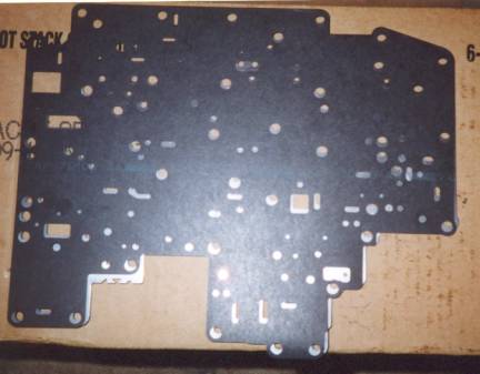
NOTE: The opposite side of the main control houses the valve body cover, shift
solenoids, TCC solenoid and the TOT sensor. Do not touch this side of the valve
body if you are modifying your current main control unit.

The main control.
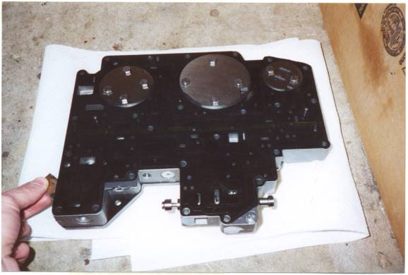
Separate the gasket from the plate using a razor blade as
shown. Discard the old gaskets.
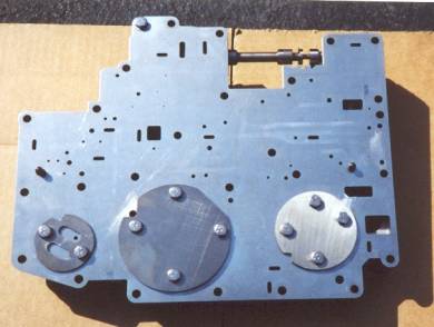
STEP #3: Using a sharp pointed object
(screwdriver), mark the indents of the three reinforcing plates (shaped like a
"Pac-Man") onto the separator plate. This is so you will easily know
how to re-install the plates later (7A008).

Prior to removal, scribe the reinforcing plate indents as
shown. Note that the flat sides face upward and the orientation of the smallest
plate.
STEP #4: You will see the separator plate
(silver) and the three reinforcing plates (round plates). The separator plate
is sandwiched between two gaskets, and secured to the valve body by 11 bolts
with 8mm (10mm head). The top gasket (7C155) is the transmission case
seal and the lower gasket is the seal between the separator plate and the valve
body itself. Remove the corner 10mm bolt and then start on the reinforcing
plate bolts. Remove the reinforcing plates one at a time and carefully clean them
with brake cleaner spray and a rag. Be sure to wear safety glasses when using
the brake cleaner spray to avoid contact with your eyes.
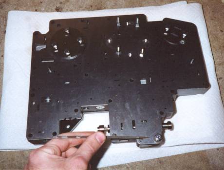
Remove the 11, 8mm (10mm head) bolts, don't forget about
this one here.
STEP #5: Remove the separator plate from
the valve body and clean it thoroughly. You now have access to the second
separator gasket (7D100). Remove it
with a razor blade in a similar fashion to the first gasket. Discard the
gasket, BUT NOT the separator plate. If your separator plate is warped in any
way, you should replace it. Remove any trace gasket material that may be stuck
to the valve body.

Lift off the separator plate to expose the valve body.
Then clean it. You can remove the second gasket in the same manner as the first
one.
STEP #6: Depending of the mileage on the
vehicle you may want to clean the valve body out (this is highly recommended).
Make a mental note of where all eight (8) check balls go before hand. Another
option would be to take a Polaroid photo or make a drawing of where the check
balls go to help you later. There is also a small screen in the corner of the
valve body and a back-out valve next to the filter bore hole. To remove the
check balls you can simply tip the valve body over into a clean bucket or a
transmission pan. To remove the back-out valve, simply use your fingertips or a
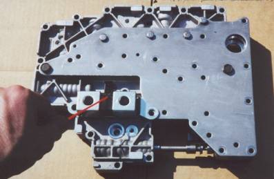
paper clip to lift it out. See the photo for details.
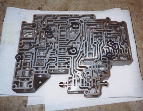
Circled are the 8 checkball locations. Above the filter
bore is the back out valve.
It is
advisable to remove each check ball individually as it will help you to
remember where they go later. Use a paper clip or small screwdriver to remove
the check balls (Do not lose any of the check balls). You can leave the small
square screen and back-out valve in, just make a note of them in case they fall
out. Spray brake cleaner spray into the
valve body maze and then tip the valve body over to release the old ATF. Re-install the check balls and back-out
valve into their proper locations. Do not lose any of these parts.
ADVICE: If
you are not familiar with the workings of the main control unit, DO NOT remove
the valves and/or springs. It is not necessary to touch the internal valves or
the manual shift valve. NOTE: If you are installing a new valve body (i.e. 1999
main control unit), you do not have to clean the valve body out or remove the
check balls.
STEP #7: YOU DO NOT DRILL INTO THE VALVE
BODY ITSELF, so place it to the side for now. You may wish to cover it with a
rag to prevent debris from entering the valve body. Follow the chart provided
to mark the hole locations and hole sizes on the separator plate. Mark each
hole with a magic marker that needs to be either created or enlarged. If you
enlarge the wrong hole, you need to purchase a new separator plate, so be
careful. Write the hole sizes down next to each numbered hole (see photo).
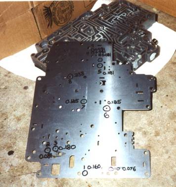
The separator plate with the holes marked and numbered.
IMPORTANT: Do not follow these hole sizes as they may vary per vehicle
application. Refer to the chart provided for hole size information. Shown is a
1995 main control at the less than 300 HP setting.
STEP #8: Replacement separator gaskets. You
need these before you start, they are available through your Ford dealer.
1994-1995
4R70W: Use, p.n. F5AZ-7D100-A. The
original p.n. on the gasket may read, F5AP-7D100-A,
the replacement is F5AZ-7D100-A. The second gasket required is, p.n. F2VY-7C155-A.
1996-1997
4R70W: Use, p.n. XW7Z-7D100-AA. The
second gasket required, is p.n. F7AZ-7C155-AA.
STEP #9: Using a soft backstop to drill
into, place the separator plate on a flat surface (i.e. a six gallon container
empty water box or workbench). Hold the plate down and carefully drill the
holes in numerical order. All drill bits are subject to breakage during use. To
minimize personal injury, never apply pressure in any direction except directly
in-line with the drill bit. Be sure to drill straight, if your drill is
equipped with a level, use it to verify your angle of entry. NOTE: Wear safety
glasses or goggles when drilling.

Drilling the separator plate. Be sure to double
check the hole and hole size before hand.
For smaller
holes in which you are enlarging to a bigger size (always refer to the chart)
you can start with a smaller drill bit. For example, if you need to make a hole
0.081" (#46), you can start with 0.076" (#48) drill. Then make the
hole to 0.081". ALWAYS DOUBLE CHECK EACH HOLE BEFORE YOU DRILL.
STEP #10: After you drill each hole,
carefully de-burr it with a file or honing stone. You may use the tip of
another drill bit to remove the burr as well. Make sure the hole is round and
not oval or oblong. Run you finger over the hole on both sides of the separator
plate to be sure it's smooth. After you de-burr all the required holes, clean
the separator plate with brake cleaner spray. Be sure to remove any filings or
debris. Line up the gasket (7D100) over the separator plate and make
sure all your holes match up.
The separator plate and gasket together.
Be sure all
the check balls are in their proper locations in the valve body before proceeding. Double check the small screen and back-out
valve are also in the main control. NOTE: Carefully inspect the valve body maze
for any debris (i.e. cotton, lint, paper towel, dirt, etc.).
STEP #11: Install the new separator plate
gasket (7D100) onto the valve body. Then install the separator plate
over the gasket. Verify each hole to make sure none are blocked. Re-install the
reinforcing plates in their proper locations. Remember to use the scribed marks
you made when removing the plates, to help re-install them. They line up only
one way, but the orientation of the smallest plate can be confusing (the indent
or "Pac-Man" faces the outer edge of the main control unit). The
plates flat side faces up, the side with the valley face downward or towards the
separator plate.
First install the NEW separator plate gasket, then re-install
the separator plate. Shown here are the reinforcing plates installed over
the separator plate. Don. t forget to use the scribed marks you made for
the plate orientation. Tighten the 11, 8mm bolts.
STEP #12: Thread all 11, 8mm (10mm head)
bolts into the holes and hand tighten them. Torque the bolts to 90 inch-pounds.
NOTE: It is very important to torque the bolts to their proper specifications.
STEP #13: Use your finger and apply fresh
ATF to the last separator plate gasket (7C155) and lay it on top of the
separator plate and over the reinforcing plates.
Then place the upper
gasket over the separator plate.
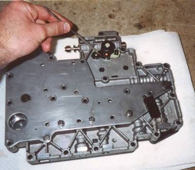
This photo shows the alignment dowels on the '94-'95 models. On
the '96-'97 models, these will be smaller. The main control is ready
to install.
NOTE: IF
YOU ARE INSTALLING A NEW 1999 MAIN CONTROL UNIT (or any new main control unit
for that matter), YOU MUST USE YOUR ORIGINAL SHIFT SOLENOIDS (7G484), TOT
SENSOR (7H141) the black plastic tab attached to the main controls cover, TCC SOLENOID (7G136), and the EPC SOLENOID located in the transmission case (7G383)*. Using the
incorrect year solenoids will result in pre-mature failure of these electronic
devices. If you need to replace any one of these parts, use the one from your
year and transmission**.
The Shift Control Solenoids (SS1 and SS2).
The Torque Converter Clutch Solenoid (TCC). Also shown is
the TOT sensor attached to the main control (black tab).
* The EPC solenoid can
be replaced with the newer 1997 version (if needed, it's not necessary). It
will fit and work properly with all '94-'97 4R70W transmissions.
** If you have a newer
transmission in your older year vehicle, most likely you have the newer style
solenoids and connectors. Always go by the transmission date.
STEP #14: Install the valve body into the transmission.
This is step # 14 in the . Shifty Business. installation report.
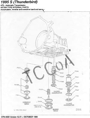
CPD drawings of the accumulators
Click on the Image to enlarge.
ADDITIONAL
NOTES: If you are
installing a new 1999 main control unit into an older transmission ('94/'95)
you must do the following.
- Use the
original TCC solenoid that came with your vehicle and install it first into its
bore.
- Use the
original Shift Control Solenoids that came with your vehicle and install them next
into its bore. Be sure to check the snouts on the shift solenoids for cracks.
If you see a crack replace the solenoid pack with the same part number. NOTE:
The shift control solenoids go OVER the TCC solenoid's bracket. Secure the two
using the 8mm (10mm head) bolt in the main control. You can discard the bracket
from your old main control, p.n. 7H186.
- Use the
original TOT (7H141) sensor that came with your vehicle. You must remove
this from your old valve body (making a note of which hole it goes into). You
may want to replace the sensor as the contact tab becomes mangled when you
attempt to remove it. Place the TOT sensor into the new main control unit cover
plate.
You will
need the main control sleeves, p.n. F6AZ-7K720-A
to install the 1999 main control into a '94 or '95 transmission case. You DO
NOT need the sleeves when installing the 1999 main control into a '96/'97
transmission case.
You also
need the newer style EPC solenoid bracket, p.n. F6AZ-7H111-A, when installing a newer main control unit (i.e.
1996-1999) into an older '94/'95 transmission. You DO NOT need the new bracket
when installing the 1999 main control unit into a '96/'97 transmission.
NOTE: The
drill bits are available through Sears Hardware or an on-line catalog company
(i.e. McMaster-Carr or Grainger). Vermont-American makes the drill bits and
sells them individually.
Special
thanks to Mike F., Steve M. and Jerry W. for their help with this report.
NOTE: I do
not assume responsibility for damaged and/or broken materials during the
modification and installation of the aforementioned parts. This document is
solely designed as a supplement to a Ford Motor Company shop manual.
NOTES ON THE SEPARATOR PLATE TEMPLATE
DRILL SPECIFICATION CHARTS - click Here
NOTE
#1: This hole, #11 (depending on your original separator plate), may need to be
created. Place the gasket (7D100) over the separator plate, so it lines
up with all the holes. Use the center of the slot in the gasket (7D100)
as a guide for the center of your hole. Mark the hole with a small point (i.e.
center punch) and drill it to specifications. If you have this hole, you only
need to enlarge it.
NOTE
#2:
When opening holes; #4 and #5, to the 450-625 HP levels (see Jerry. s thesis
for these levels), you must open up the holes in the gasket as well. Ignore NOTE
#2, if you are opening the holes to less than 450 horsepower.
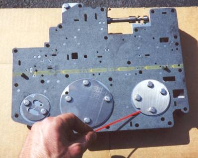
NOTE
#3: This is the location of the #8 hole on the 1994-1997 separator plates. This
hole must be enlarged on the 1994-1995 main controls. 1996 and up 4R70W
transmissions do not have to change this hole size. The hole is located further
down from the 1998 and up separator plates. The arrow points to the proper
location for all (factory) 1994-1997 4R70W transmissions.
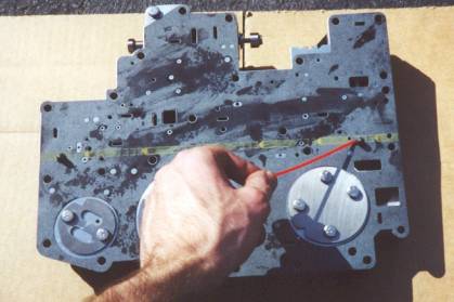
NOTE
#4: There is a very small gasket slot in this location (arrow points to it).
This is slot number 1 on the drill specification chart. Open this slot to the
correct size based on the chart and your application. If you are opening the
holes to the less than 300 HP range, you DO NOT have to change this slot.
NOTE
#5: If you have a mechanical diode intermediate one-way clutch, you can
open hole #6 in the separator plate to
a slot. Use the slot in the gasket as a guide and make several holes together
to create the slot. ALL 1994-1997 4R70W factory transmissions DO NOT have
the intermediate one-way clutch mechanical diode ( MD OWC). If you do not have
the MD OWC , open your hole to 0.125. (1/8. ).
| Sponsor Links |
|
|
|