| Alternatively Flashing Lights |
 |
 |
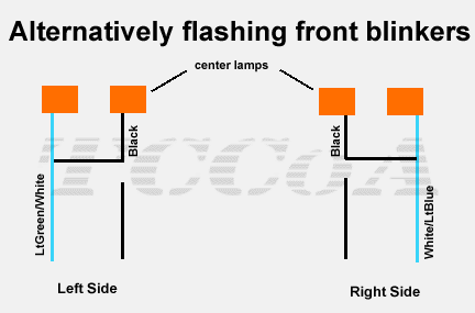
Here is a little system of alternatively flashing lights that is the best alternative for the sequential lights for cars '94 -'97, since they are design with possibility to flash independently. Here are two pictures of how this looks
The whole system is based on using a ground signal of on light that doesn't blink and routing it to the blinker signal of the light that blinks.
How does it work ?! Easy. As the steady lamp receives ground (-) and positive signal from the car it lights up when you put the head lights on. When the blinker is OFF, its not receiving any positive signal so it stays negative(-) all the time until you activate it. So if you hook up the ground of the steady lamp to the blinker signal it will act normal as long as the blinker is off since it has negative(-) signal all the time.
Once the blinker is activated, it gets a positive(+) signal from the car. As blinker gets positive(+) signal and so is the steady light cause they are both connected. As the steady light gets 2 positive signals (one from the car and the other from the blinker) it shuts off. And vice-versa. If the blinker is off, panel comes back on. Remember: positive and negative have to interact with each other for the circuit to work.
Note: This system works ONLY if you have the headlighs or parking lights on. When they are OFF (during daytime) the light act normal as they came with the car. You may say that you would like them to blink like that during the day but they have no use in the daytime cause u can hardly see them flashing in the daytime cause the signal is not as strong as if you would light up the brake lights.

- On the front headlights, cut the ground wire that runs to the center lamps
- Take the bulb side of that black wire, extend it using another piece of wire that you can buy at any Radio Shock, and route it to the blinker lamp (12" should be enough).
- Blinker should have 3 wires running to the bulb: one ground, one driving light signal and a blinker light signal. You are interested only in the blinker signal wire.
- Strip some of the wire sleve off the blinker trigger wire which in this case has a LtGr/Wh and Wh/LtBl color. Don't cut it like the for the center lamp; just strip it.
- Take that ground signal wire from the center lamp that you prepared early, run it to the blinker and just connect it to the stripped piece of blinker signal wire.
- Take some electric tape and tape up everything.

- On the rear headlights it works the same as for the fornt. Cut the ground wire (wh/yl - white with yellow stripe) that runs to the panel lights.
- Take the panel side of that wire, extend it using another piece of wire that you can buy at any Radio Shock, and route it from the trunk lid down the wire loom to the blinker lamp (6-7' should be enough).
- Blinker should have 3 wires running to the bulb: one ground, one driving light signal(brown) and a blinker light signal(Lg/Or & Or/LtBl). You are interested only in the blinker signal wire.
- Strip some of the wire sleve off the blinker trigger wire. Don't cut it like the for the panel lights; just strip it.
- Take that ground signal wire from the center panel lights that you prepared early, run it to the blinker and just connect it to the stripped piece of blinker signal wire.
- Take some electric tape and tape up everything.
Side Effect: As you step on the brake pedal, corner lamps light up stronger and the panels stut off. It really makes stoping fun for the person in your rear view mirror. He will sure admire the unique creation.
The system shouln't be of any harm to your car or the circuit if you connect evrything together well. I have heard of people blowing fuses, but that was a mistake on their side.
Additional notes by Scott Anderson:
First, it is much easier to do the wire splicing if you remove the turn signal assemblies. Two 10 mm nuts and they come right out. Also unplugging the inboard lights makes access to the wires easier. 18 gauge wire should do and you will need about 24" instead of 12" if you want to route it along the harness. I cut the wires and used weather proof heat shrink solder filled terminals that I found at Pep Boys (Conduct Tite #85272). The bulb housing are identified in the article as "ground", "minor", and "major". The "major" wire is the one that is shown as the "blinker trigger" in the article.
| Sponsor Links |
 |
 |
|
|
|
|

|